
J and E Engineering Services Ltd.
Unit 32 Britannia Mill,
Stoneholme Road,
Crawshawbooth,
Rossendale,
Lancashire.
BB4 8BA.
Monday
Tuesday
Wednesday
Thursday
Friday
Saturday
Sunday
8:30am -
8:30am -
8:30am -
8:30am -
8:30am -
9:00am -
Closed















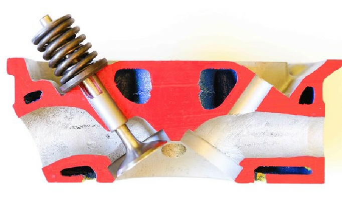
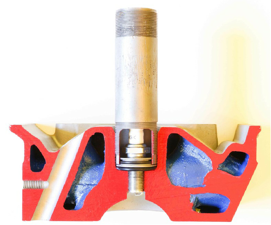
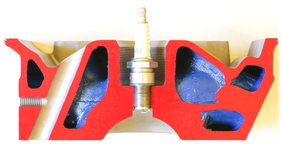
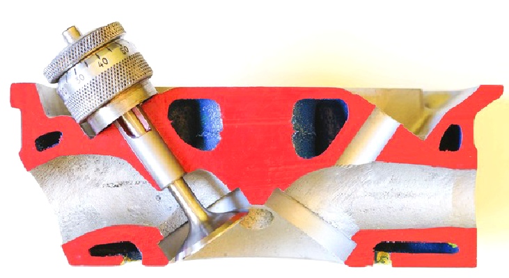



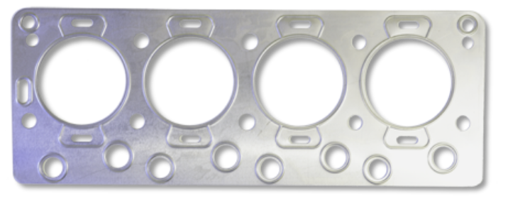
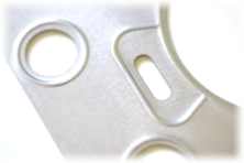
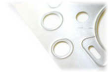
The standard cylinder head gasket is a single layer steel (SLS) with embossed sealing crimps around the combustion chambers, water passages and push rod tubes. This gasket type is often criticised for its unforgiving nature as it is a very simplistic construction. The reality is a very effective sealing method that is now utilised in many modern engine designs. Main advantages over fibre, composite or copper gaskets are:
The main drawback that the SLS gasket has over fibre, composite or copper gaskets is that it has very little ability to conform to surface imperfections, warp or waviness within either the cast iron cylinder block face or the aluminium cylinder head.
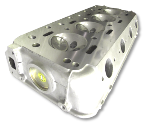
Here you can see a library image of a Daimler cylinder head that has been re-

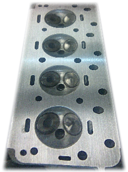
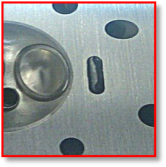











We have learned that when using the SLS cylinder head gasket the surface finish of the cylinder head (and block) is critical in order to achieve a good and long lasting seal. This is why the cylinder head gasket mating surfaces should be resurfaced in the correct way to ensure that a precise surface roughness is achieved. The SLS gasket requires a surface roughness of no more than 30 µin (Micro inches) Ra (Roughness average) or 180 Rz (Mean roughness depth) Smoother is always better for this type of gasket and can be into the low teen or single digit figures if achievable. Waviness should obviously be kept to an absolute minimum as should flatness. A Daimler V8 cylinder head has a maximum allowable “out of flat (warp)” of 0.004” / 0.1mm across the length and 0.002” / 0.05mm across its width. If all these tolerances can be met the cylinder head can be sealed with the SLS gasket very effectively.
Here you can see our cutaway cylinder head cross section 3/11. It has been mounted on the resurfacing machine and fly-
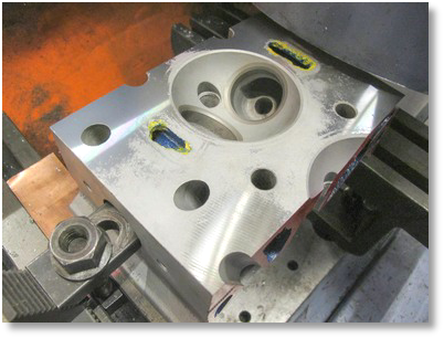
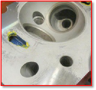

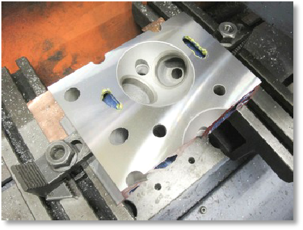
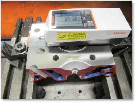
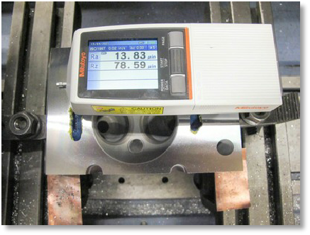
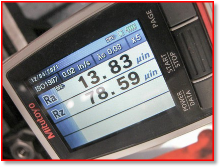

In order to achieve these desired numbers for surface finish we need to be able to measure surface roughness. Once the surface of the cylinder head is flat and all the imperfections have been removed we can test the surface with a profilometer. This is a very accurate unit that will measure the minute peaks and valleys of the freshly machined cylinder head gasket face. As you can see from the test results, we are well within the recommended parameters which will enable the single layer steel (SLS) head gasket to seal correctly and provide a long service life. Anything less will not do. Do not underestimate the importance of surface finish.

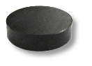
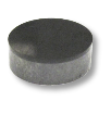

The Daimler V8 engine does not utilise a valve stem oil seal as standard. A valve stem oil seal grips around the valve stem while allowing the valve to open and close smoothly. This seal stops engine oil travelling down the valve stem and into the combustion chamber where it is burnt. The puff of blue smoke on start up and overrun is the result of this problem and can be a common complaint with owners. As the valve guide wears this problem is amplified. The standard valve guide is a hard ductile cast iron (SG) smooth wall construction which requires a clearance of around 0.002” /0.003” to allow the valve stem to slide smoothly as it opens and closes. As the valve guide and valve stem wears this clearance is unavoidably increased which allows oil to pass. The rocker action causes most of the valve guide wear here. With this information in mind we have two problems to solve:


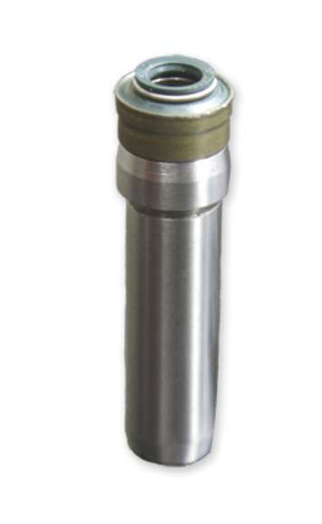
The common denominator here is the guide and this is where the modifications take place. The original valve guide was made from SG Iron an advanced material at the time which is very hard and difficult to machine. Therefore we have to remove the valve guide and replace it with a standard grey cast iron guide which can be machined easily. Prior to fitting the guide we machine the top to accept a modern valve stem oil seal with garter spring. Once the outside machining is complete the new guides are pressed into the cylinder head up to a shouldered stop. At this stage and using this type of valve guide we have actually downgraded the specification as the new cast material is nowhere near as good as the original SG Iron material used originally. This is why we fit genuine K-
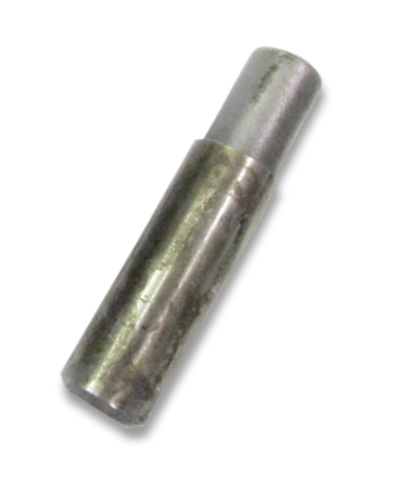
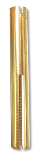
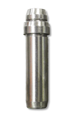
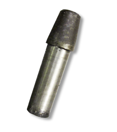


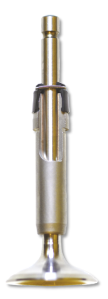
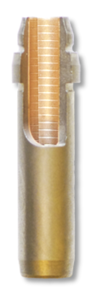
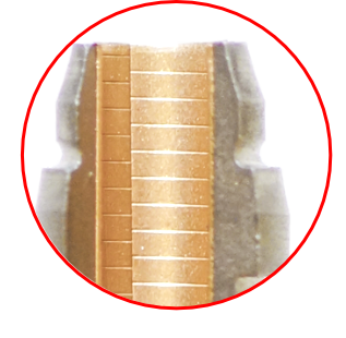



Here is a cut-

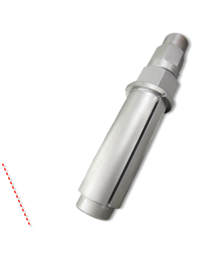
Once the valve guides have been modified the valve seat geometry must be restored so that it is concentric with the guide bore. This cannot be achieved with the use of lapping sticks and carborundum paste they must be re-
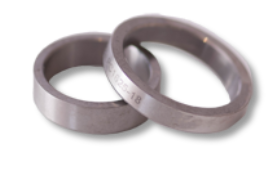
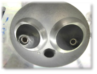
Old valve seats are removed by cutting them out to prevent damage to the aluminium.
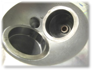
We use a Hi-
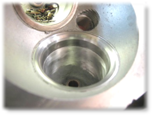
The seats are then cut to the correct depth and seat angle arrangement to ensure perfect seat sealing. The guide is used as a datum for this operation and ensures concentricity.
When cutting valve seats and replacing valves it is very important to keep in mind the relationship between this operation and the valve spring. Seats cut too deep or badly worn valves will cause valve spring seating pressure to be relieved. This can cause valve spring bounce which can lead to valve or valve seat failure. A seat which is not cut deep enough can result in a spring coil binding situation. This will lead to valve / guide failure guaranteed. This is why we need to observe the valve spring fitted height or installed height to ensure that seating pressures are maintained and coil binding is avoided.
This image clearly shows how excessive valve seat cutting will directly effect valve spring pressures. Cylinder Head section 7.
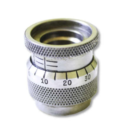

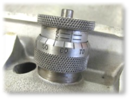
Here are some tools that we use for measuring valve spring installed height and valve spring pressure at seating and full lift situations. By doing this we can ensure that spring will not bounce and that coil binding is avoided.
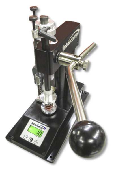
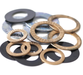
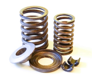
Valve spring shims and platforms can be used to correct spring pressure and balance springs. These generally come in three different thicknesses: 0.015”, 0.030” and 0.060” and are used to compensate for valve seat cutting.




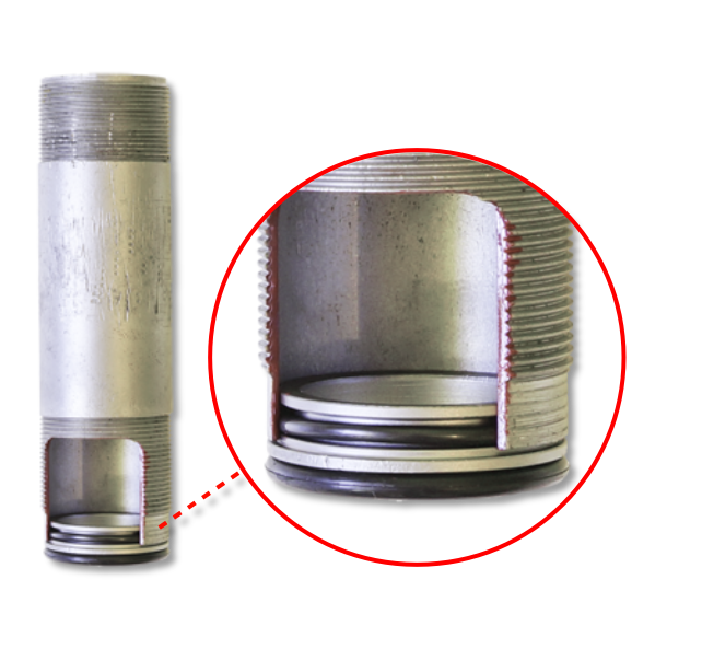
The nature of the cylinder head design and the central spark plug within the combustion chamber makes oil sealing a bit of a problem. Originally the removable spark plug tube was sealed with the use of a copper washer at the base of the retaining thread around the spark plug. Oil leaks from this area have plagued owners for many years and simply replacing the copper washer has proven unsuccessful. We now supply and fit a sealing ring which uses Viton rubber O’rings within the plug tube and around the plug tube seat. The image on the left shows a plug tube with a section cut-
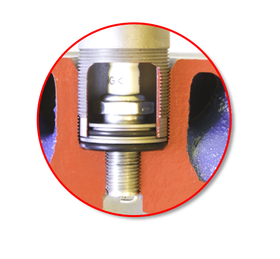

“A picture speaks a thousand words” Our new uprated spark plug tube seal can be seen in the image above. The sealing ring can be re-

 Back to Page 1
Back to Page 2
Back to Page 1
Back to Page 2