
J and E Engineering Services Ltd.
Unit 32 Britannia Mill,
Stoneholme Road,
Crawshawbooth,
Rossendale,
Lancashire.
BB4 8BA.
Monday
Tuesday
Wednesday
Thursday
Friday
Saturday
Sunday
8:30am -
8:30am -
8:30am -
8:30am -
8:30am -
9:00am -
Closed

















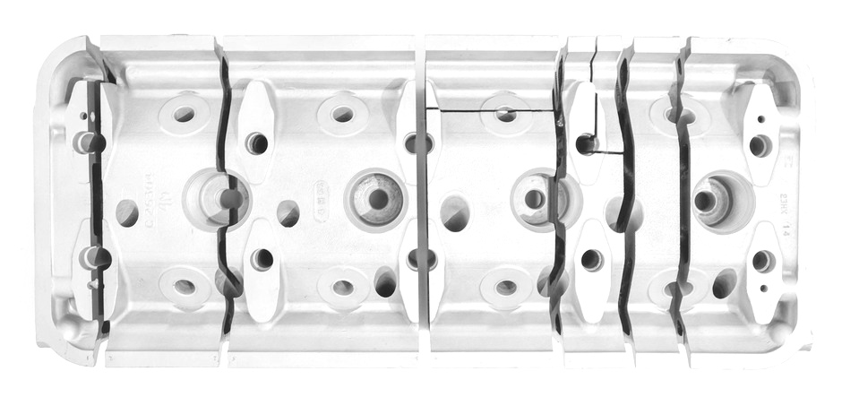






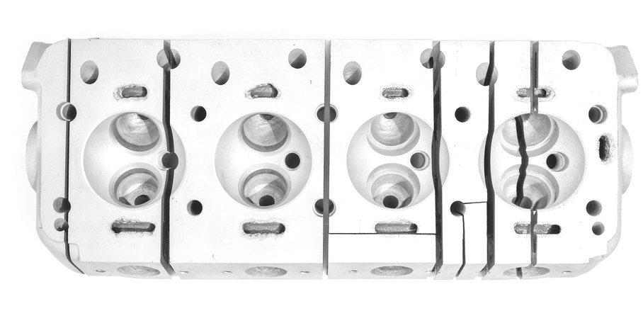

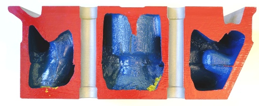
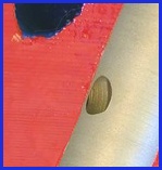
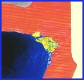
Our first sighting of internal corrosion in two locations can be seen in this cross sectional view. Also visible is the middle casting seam where the two halves of the mould were fitted together. The two vertical drillings are again for the cylinder head fixings. Note the larger machined upper and lower areas of the drillings to accommodate the location dowels of which there are many.





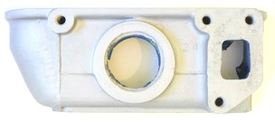
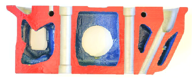
On the left is the vary familiar sight of one end of the cylinder head with core plug removed. The cylinder heads are ambidextrous and only require the fitting of a water blanking plate at the rear and oil feed blanking plugs fitted to the front in order to make them fit either right or left hand banks. The image on the right is a much rarer view and is of the same end viewed from the inside. The two vertical drillings are where the cylinder head bolts/studs would reside. The water cavity coloured blue actually wraps around the end of the head allowing coolant to circulate from side to side. The oil feed drillings can be seen which provide oil to both inlet and exhaust rocker assemblies. The diagonal tube on the right is an oil drain back tube which allows spent oil to return back to the sump.
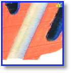
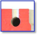



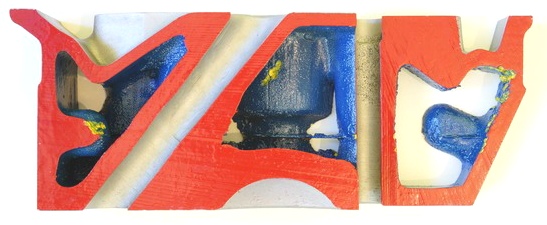
Note the push rod tube in this sectional view is at a different angle to the one in section four. This one is for an exhaust rocker while the less inclined tube is for an intake rocker arm. More corrosion can be seen as well as a more defined casting seam line. The bulb like shapes on either side is where a threaded hole is located for the fixing of intake and exhaust manifolds.
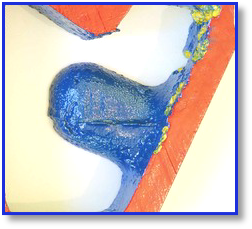
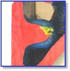
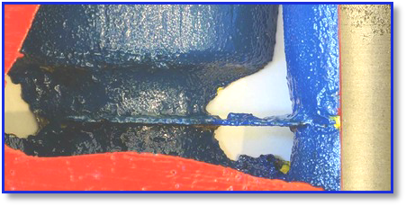
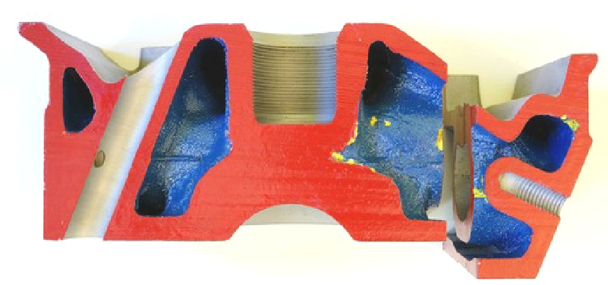
Here again you can see the third cylinder combustion chamber and spark plug tube retaining thread. This section has been cut in two places across an area of concerning corrosion against the exhaust port. We will view this in greater detail later in the autopsy. Again you can see an inlet manifold fixing hole breaching the push rod tube. The threaded hole on the right hand side is an exhaust manifold fixing point.


Here is a map for your orientation. It shows the sectional cuts of the cylinder head and the direction that each section is viewed. Watch the video above for a brief idea of how the cutaway cylinder head works. Hopefully you can make sense of it all.
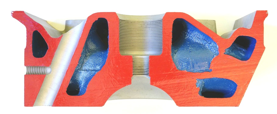
Here a cross section of the famous hemispherical combustion chamber can be seen. The spark plug thread and much larger spark plug tube thread and seat can also be seen. The large bore diagonal drilling on the left is a push rod tube. Note how the inlet manifold securing bolt thread actually breaches the tube. A possible cause of oil leaks and intake air leaks? A large coolant cavity around the exhaust port helps heat transfer into the coolant.



With all the above information in mind and the evidence speaking for itself I think it would be interesting to perhaps X-
We do however have a saw!
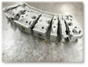
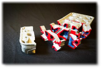

Cutaway Cylinder Head Click to view the video.
We will start with a scrap Daimler V8 saloon cylinder head and cut it into sections. The video on the right shows the cylinder head in component form and you will notice that it has been painted to make the different areas easily identifiable. Some valve seats and valve guides have been removed to enable the head to be cut. Use the pause button to view the different segments






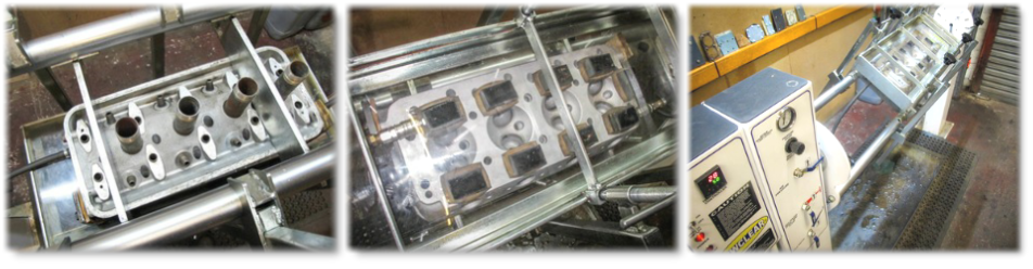
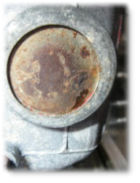
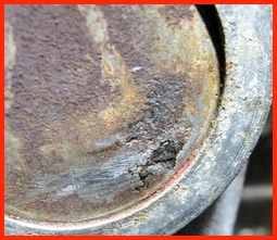
Here you can see the same cylinder head during the pressure test procedure. The head is mounted onto the machine and clamped using rubber blocks and a transparent plate which allows for combustion chamber and gasket face observation. Compressed air is then introduced inside the cylinder head as the first stage air test. Second test involves filling the cylinder head with hot water and then pressurising the cooling cavity within the head. Any cracks, flaws or porosity are indicated by water/air leaking on the outside of the casting. Images on the right indicate a leak around the core plug area as you can see. This is of course a straight forward repair and simply requires the core plug to be replaced. Corrosion is probably to blame as the core plug has rotted from the inside. Again an indication of poor corrosion inhibitor within the coolant system.
The video on the right shows the cylinder head with water and air pressure applied to the cooling cavity within the cylinder head. You can see where this cylinder head is porous and I am sure you will understand the implications this would have if put back into service. The repair for this type of issue is much more difficult than welding a crack or replacing a core plug. Yes we could weld this area and replace the bad metal with good. The problem is porosity in other areas just waiting to break through. I don't think that this problem would have been apparent when the head was new. It is more likely that the dreaded corrosion has eaten its way through the aluminium.


Porous Cylinder Head Under Test Click to view the video.
Porous Cylinder Head Under Test Click to view the video.
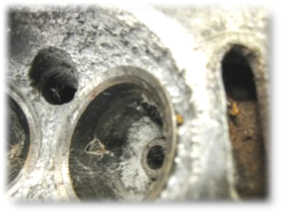
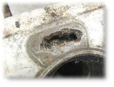
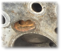
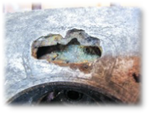
Classic Daimler cylinder head corrosion can be seen around the water coolant passages. This can range from mild to severe and can be caused by dissimilar metal electrolysis. The cylinder block is cast iron and iron particles are circulated around the whole cooling system, notice the orange rust colour inside the alloy water passages. This effect can be combated by ensuring your engine is equipped with a good corrosion inhibitor found in good quality antifreezes. For some however it may be too late. These problems can be addressed by tig welding the aluminium cylinder head around the damaged areas. This can be a difficult and time consuming process as impurities in the aluminium are plentiful. The extreme temperatures required to weld are also very stressful for these old cylinder heads and distortion will occur. Interference fits with valve guides and valve seats can also be compromised and so care must be taken.
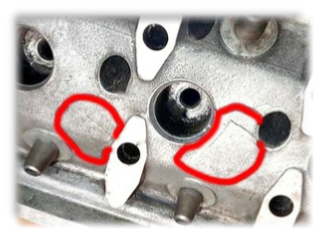
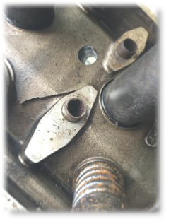
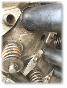
Above images show cracks on the top cylinder head face underneath the rocker gear. These are caused by freezing coolant within the water jacket sometime in the past. Most Classic Daimlers wont even see freezing temperatures these days as they have become well loved and somewhat better taken care of than they may have been in a previous life. When the coolant freezes due to a weak or non existent antifreeze mixture the coolant will expand greatly and because of the sealed system the extra volume has nowhere to go. Hoses will expand with the freeze as they are made of rubber which leaves only the thin wall casting of either the cylinder block or cylinder head. This is one of the more serious repairs and again can only be repaired by aluminium welding in the case of the cylinder head. Again distortion and stress are the enemy and a fair amount of post machining may be required to reinstate rocker shaft platform heights, valve spring seats and plug tube seating. Rocker shaft breakage will occur if all of the platforms are not parallel.

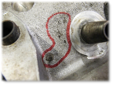


As if all the above does not demonstrate enough of the problems that can occur with Edward Turner’s V8 engine, casting porosity is without doubt the most difficult to identify. The rather innocent looking image here on the right shows an area marked with black, dirty looking spots. These are indeed flaws in the alloy casting straight through into the coolant cavity. The only way to identify this problem is to have your cylinder heads pressure tested. This should be the first phase before any work carried out on the cylinder head and lets us know exactly what we are dealing with. There is no point in rebuilding cylinder heads that have a hidden fundamental flaw that will cause issues when put back into service.

The aluminium cylinder head(s) can be a real problem for these beautiful V8 engines. Damaged combustion chambers, porous castings, worn valve guides, burnt out valves, corrosion and cracks are all relatively common occurrences. Valve guides and seats can be repaired fairly easily while corrosion porosity and cracks can be difficult and costly to repair.
Above you can see some “Burnt-
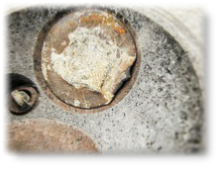
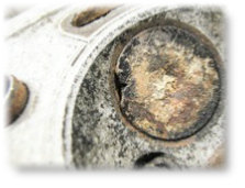
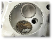
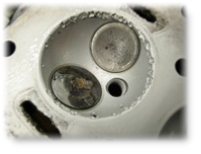
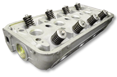
Here you can see significant combustion chamber damage caused by foreign body entrapment within the cylinder. This can come from the carburettors, spark plug failure or piston/ring break up. Bent valves and damaged cylinder wall will result. Extreme cases can result in a water jacket breach. Something that should be avoided.
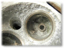
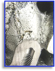
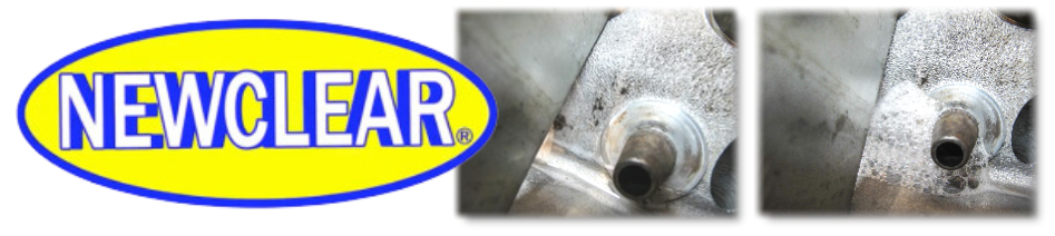
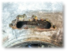
Here a badly corroded combustion chamber has left the valve seat exposed around the edge. This has probably been caused by poor storage with a cylinder full of water or a leak or drip directly on to the chamber. The aluminium has been eroded away.










 Page 2