
J and E Engineering Services Ltd.
Unit 32 Britannia Mill,
Stoneholme Road,
Crawshawbooth,
Rossendale,
Lancashire.
BB4 8BA.
Monday
Tuesday
Wednesday
Thursday
Friday
Saturday
Sunday
8:30am -
8:30am -
8:30am -
8:30am -
8:30am -
9:00am -
Closed










































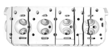















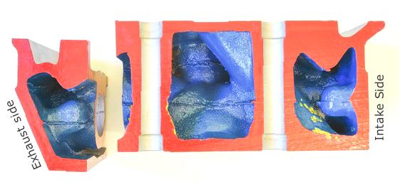
This slice again shows the cylinder head fixing drillings with dowel counter bores top and bottom. On the right hand side you can see how the casting accommodates the exhaust push rod tube and again the mould seam is clearly visible.
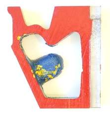
Another smaller cross section was taken to allow a better understanding of how the coolant is circulated around the exhaust port.
A surprising feature of this section is just how thin the alloy wall thickness is underneath the exhaust port only 0.157”/4.00mm this must be taken into consideration when re-
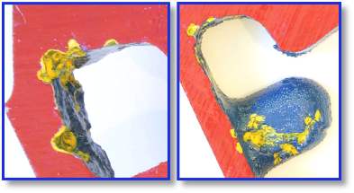
The second face of the small cross section shows the inclined valve guide bore hole, valve spring seat and the now all familiar coolant passage that allows for movement between the cylinder block and head. These are the areas that are usually repaired by tig welding. Less easy to repair is the corrosion eating its way through the exhaust port wall. Some people like to re-
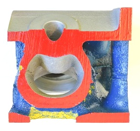
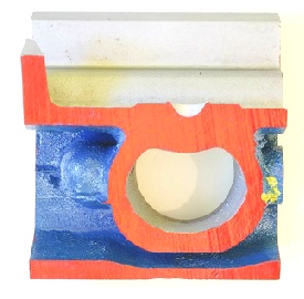


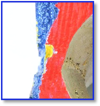
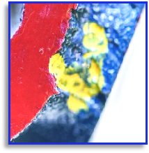
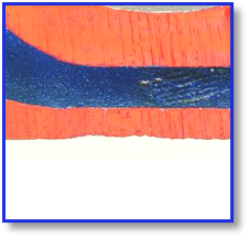
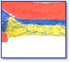


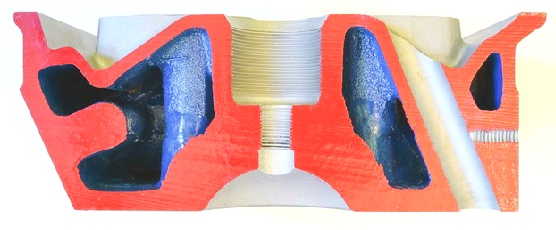
Section 11 shows us perhaps the best example of the intake manifold securing fixing breaching the push rod tube. The spark plug tube and spark plug threads can also bee seen in section. Note the seating area where the spark plug tube sits and is supposed to seal with a copper washer. There is a tapered radius in the bottom which may be a restriction when tightening the plug tube. No real signs of corrosion here and you can see the rocker shaft platforms and cylinder head fixing tubes within the casting.
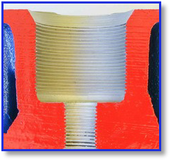
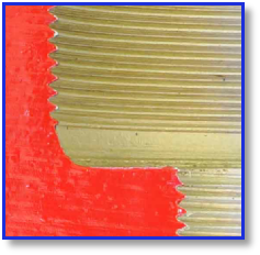


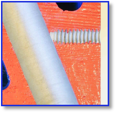

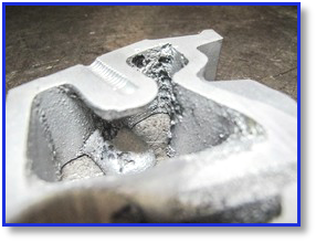
Here is our old friend corrosion again and as you can see it has penetrated about half the alloy wall thickness. This area was one of the most badly corroded internal areas I came across and I even cut an additional smaller cross section to help reveal the extent of the damage
The overall wall thickness in this area measured 0.267”/6.78mm
When measured in the corroded area it measures just 0.105”/2.67mm a loss of 0.162”/4.11mm!



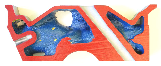
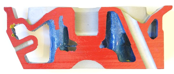
Here you can see a truly cavernous coolant chamber concentrated around the hot exhaust port. Some quite deep corroded pitting is hi-
The aluminium was measured at just 0.184”/4.68mm total thickness above the exhaust port and could be the reason for cracking in this area.


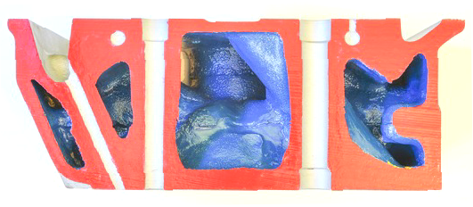
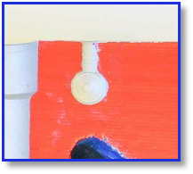
Here you can see the large coolant cavity around the combustion chamber an area that certainly needs to be cooled. Also visible are the oil feed drillings to the rocker gear. The oil drain back tube can also be seen relieving the cylinder head of unnecessary oil quantity. The wall thickness in between the rocker pedestal platforms is only 0.165”/4.2mm one of the thinnest areas in the head and possibly the reason for any frost cracks appearing in this area.

This concludes our journey of cross sectional views through the Daimler V8 cylinder head. I hope you have found it interesting. We will now look closer at some of the repair methods that can be used to rectify the issues the autopsy has taught us
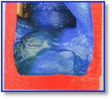


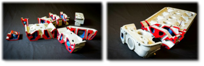
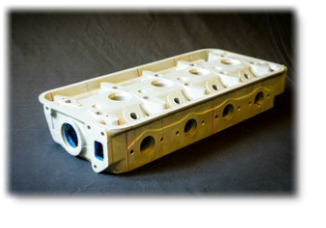
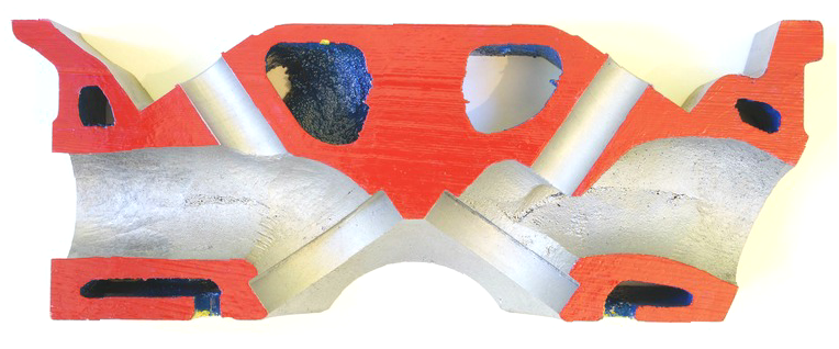
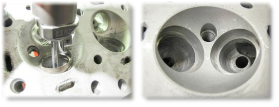
This is an interesting section with the cut being made through the centre of the combustion chamber. The valve seats and guides had already been removed as they are a hard material and would have dulled the saw blade. You can clearly see the valve seat counter bores and the valve guide housings. You may also notice that the intake port tract is slightly longer than the exhaust. This is because it has a slight bend in it in order to avoid a push rod tube. Also of note is the coolant cavities underneath each port. This is a critical area where most cooling is required. The valve uses the valve seat and guide to disperse 75% of its heat which in turn passes to the coolant. Below are images of the valve seats being machined out and a combustion chamber without valve seats prior to cutting.
Contrary to popular belief the valve seats fitted to these, later saloon cylinder heads are not “dove-
The dovetailed seats as in the motorcycle heads have a 0.003”-

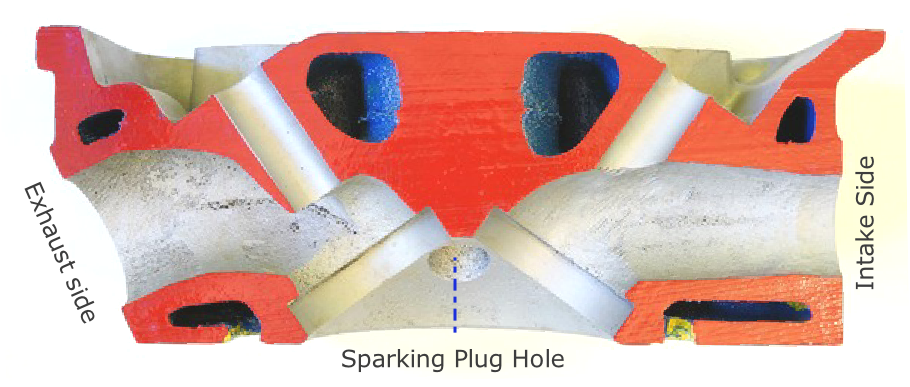
We are now heading back through the cylinder head in the opposite direction. Note the inlet and exhaust orientation has now changed. In this section we can once again see the inlet and exhaust ports with combustion chamber. The spark plug hole is now visible as is the coolant cavity that encircles the spark plug tube. Interesting how the intake port is narrow at the manifold flange end. Also of note is the different length of valve guide bore holes. It is however the intake valve guide which is longer than the exhaust guide even though it is offered less support. Once again the thin wall thickness between coolant cavity and valve train section of the head is clear to see.
This is the end of the line for the first phase of the autopsy. We will be travelling back through the cylinder head to look at the other side of the cross sectional views.
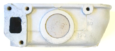
At this end of the cylinder head you can see the core plug in place. These core plugs are an old style dish type that rely on a small surface area to create a seal. Once placed in the hole the dish is flattened somewhat to increase the outer diameter and hold it tight. This type of plug is also used in the cylinder block. The fitting in the cylinder head is somewhat different I think in order to combat thermal expansion problems when using aluminium as is the case of the cylinder head. Once the core plug had been fitted the outer aluminium was then rolled over or burnished against the newly fitted core plug which stopped the plug popping out under pressure. The trouble is when the core plug is removed it unavoidably breaks off the small thin ring or rolled aluminium that used to retain it.
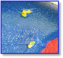
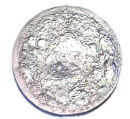
The image on the left shows the core plug that was removed from the other end of our cylinder head. The reason it looks like the surface of the moon is once again down to our old friend corrosion. Core plugs will corrode from the inside out so don't be fooled by a good looking outer appearance.
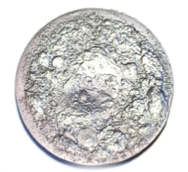
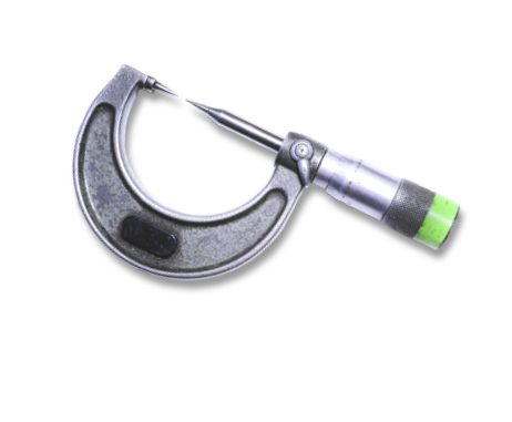
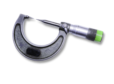
Using this Pin micrometer we can measure the different thickness to evaluate how much corrosion has taken place.
The undamaged part of the core plug measures 0.082”/2.08mm
The Most corroded part measures 0.012”/0.30mm
Remember the leaking core plug found during pressure testing? This is why you should always replace all core plugs when re-

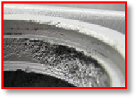



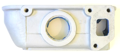
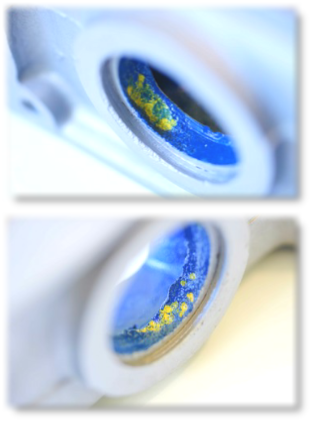
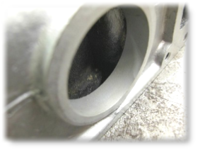
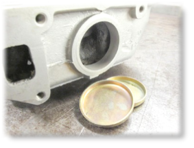
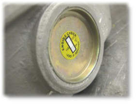
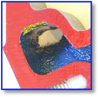
Here you can see where the aluminium behind the core plug has been corroded. This corrosion has just started to penetrate the sealing platform of the plug and so a leak is not far away. In order to use a “cup” type rather than a “dish” type core plug, the former having a greater surface sealing area, the aluminium requires machining as shown below left. This image shows the newly machined surface and any corrosion removed ready to accept the new core plug. The same can then be carried out for the opposing end of the head. No external rolling or burnishing is required with this type of plug and it is used widely in modern engines using both cast iron and aluminium cylinder heads.
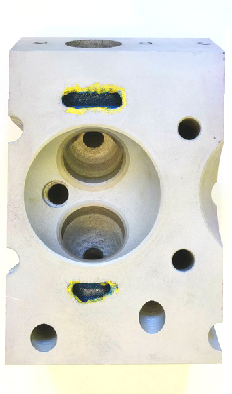
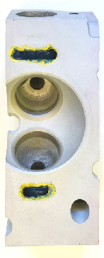
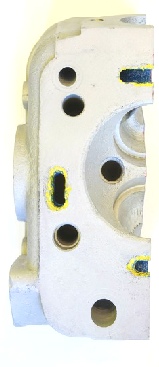
Surface corrosion around the water passages on the head gasket face can be repaired by tig welding. Aluminium welding is very susceptible to impurities in the parent meal and it is this that makes the procedure problematic. Oxidised, old cast aluminium is full of these impurities. First of all we dig out the corrosion and cut back to good metal if possible. The cylinder head is then pre-
Welding internal corrosion is however a different matter……..


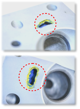

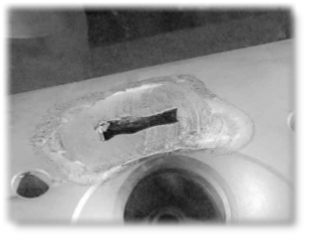
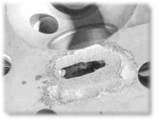
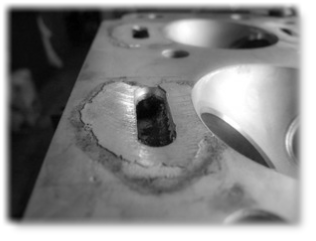

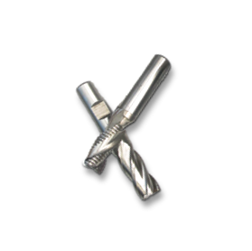
The video here on the left shows our CNC vertical machining centre opening up the water passages back to the correct size. The first cut is a roughing cut followed by a fine finish cut.

Click Here To View The Video

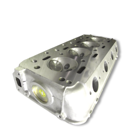
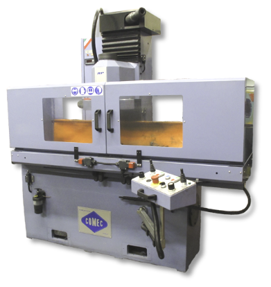
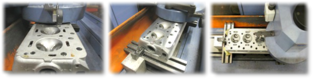
Once the welding repairs have been completed the cylinder head gasket surface will require “Fly-



 Back to Page 1









 Back to Page 1
To Page 3