Copyright © 2026 J and E Engineering Services Ltd All Rights Reserved








J and E Engineering Services Ltd.
Unit 32 Britannia Mill,
Stoneholme Road,
Crawshawbooth,
Rossendale,
Lancashire.
BB4 8BA.
Monday
Tuesday
Wednesday
Thursday
Friday
Saturday
Sunday
8:30am -
8:30am -
8:30am -
8:30am -
8:30am -
9:00am -
Closed
















Adjusting the tappets or valve clearances can be a difficult and time consuming task that some people can find quite daunting. It is however a very important maintenance procedure and one which should be carried out on a regular basis to ensure correct engine running and performance. On this page we will discuss the procedure that we use to adjust the valve clearances. This is the most simple method and requires the minimal of crankshaft rotations.

The left hand bank is the bank of cylinders on the left when sat in the car or viewed from the rear. This would be the nearside or passenger side in a right hand drive car.
The left hand bank is further forward that the right hand bank because of the connecting rod offset.
The right hand bank is the bank of cylinders on the right when sat in the car or viewed from the rear. This would be the offside or drivers side in a right hand drive car.
The crankshaft rotates in a clockwise direction when viewed from the front.
The camshaft rotates at half crankshaft speed. This means the crankshaft needs to rotate two complete turns, 720° in order for the camshaft to rotate one full turn 360°.
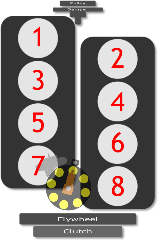
The correct cylinder numbering is 1 to 8 from front to back. This means that all odd cylinders 1,3,5,7 are on the LH bank and all even cylinders 2,4,6,8 are on the RH bank. (See diagram below).
The correct firing order for the Daimler V8 in correct numerical order is: 1,8,4,3,6,5,7,2.
With the piston on the compression stroke at Top, Dead, Centre (TDC) both inlet and exhaust valves are closed and their clearances can be adjusted at the same time.
Inlet clearance .011” /0.28mm
Exhaust clearance .014”/0.36mm

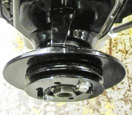
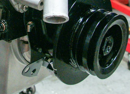



Turn the engine clockwise until the timing reference marks & pointers align. Note these marking locations differ between Saloon and SP250 models see images above. At this point you may need to make the reference mark on the damper wheel more easily visible. This can be done by scraping the mark indentation clean with a hacksaw blade or a dab of paint/marker. With this done number 1 cylinder (LH1) will be at TDC. However it may not be on the compression stroke which is the required position to set the clearances. Remove the distributor cap and note the rotor arm position. Compare the rotor position to the corresponding segment/Plug lead of the distributor cap. You will find by tracing or following the same plug lead (HT lead) that you will end up at either number 1 cylinder (LH1) or number 6 (3R). If the rotor arm points to the number 1 cylinder (LH1) plug lead you are ready to adjust both inlet and exhaust valve clearances on that cylinder. If your rotor arm ponts to number 6 (R3) cylinder this means you are 180° (Camshaft) from the starting position and you will need to turn the crankshaft one complete turn and realign the timing marks of the pointer and damper. After doing so your rotor arm should now be pointing to number 1 cylinder plug lead segment. The valve clearances on number 1 (LH1) can now be adjusted.
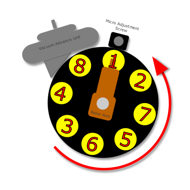



With the first pair of clearances adjusted on cylinder 1 (LH1) we can move on the the other cylinders. We know that the crankshaft needs to turn 720° in order for the camshaft to turn 360°. This would be a full engine cycle, each of the eight cylinders completing the four strokes of inlet, compression, power & exhaust. From this information we have the following calculation:
720° (Crankshaft rotation) divided by 8 (cylinders) = 90°
This means we can adjust a pair of valve clearances for every 90° of crankshaft rotation in the firing order sequence.




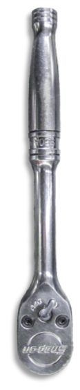
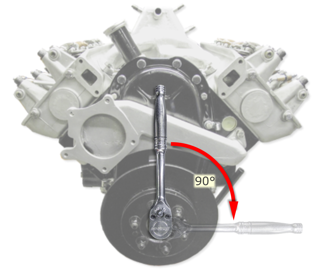
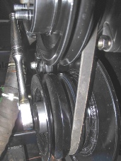
The fact that a pair of valve clearances can be adjusted every 90° is a good thing as it is a simple angle to visualise. There needs to be a certain amount of accuracy when turning the engine by 90° however and for this we use a 1/2” drive ratchet handle as seen below.
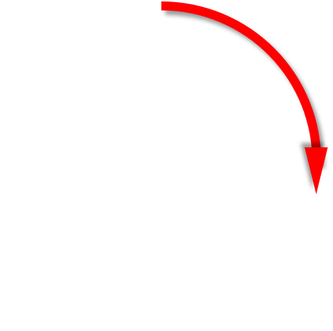
Using the ratchet, position the handle precisely at the vertical or 12 O’clock position then turning the engine clockwise 90° to the 3 O’clock position accurately. Now the second pair of valve clearances can be adjusted in the firing order, this would be cylinder 8 or RH4.
It is worth noting that if you overshoot the 90° rotation with the ratchet you shouldn't turn back (Anti-
Once the clearances have been checked / adjusted, re-
Continue this method until you have completed two full turns of the crankshaft and all 16 valve clearances have been checked and or adjusted.
Note: for every four 90° turns, the timing marks should realign to the TDC reference. This allows you to check your progress and will show you how accurate your 90° turns have been to this point.






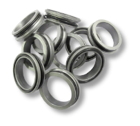
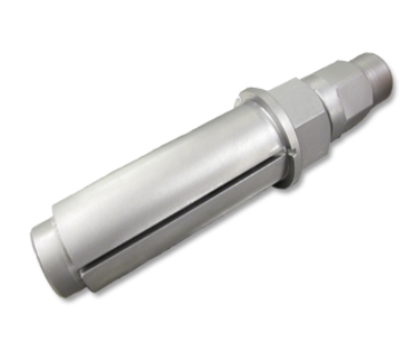
Spark plug tube removal tool and modified seal kit allows for easy tube removal and refit, freeing up some much needed space when adjusting the tappets. Our plug tube sealing arrangement allows regular tube removal & refitting as required without having to apply permanent sealants.

We offer a full range of tools and parts that you may find necessary to complete the tappet adjustment procedure. These are listed below and can also be found on the ‘Parts & tooling’ pages of this website.
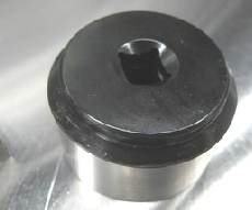
Low profile 3/8 drive socket for the crankshaft nut. This helps with the turning of the crankshaft in a space limited area. Particularly useful for the V8 saloon in between the fan and belt arrangement.
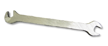
Double ended offset crank spanner of the correct size as indicated in the workshop manual. This fits the square adjustment screw perfectly and allows for precise adjustment prior to tightening the lock nut.
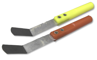
Cranked feeler blades of the correct thickness with an integral colour coded handle. Red for exhaust clearances and yellow for the intake clearance. No more fumbling around with multi-
Intake: .011”
Exhaust .014”
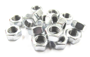
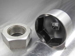
Replacement lock nuts of the correct size, 7/16 AF as original (Not ½ AF as supplied by the big parts suppliers) available individually or in complete sets of 16. You will often see rounded off lock nuts which cannot be tightened correctly and make valve adjustment difficult. These are direct replacements.
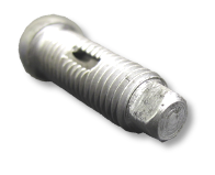
We also offer replacement adjustment screws from our vast stock of second hand parts. These too are often rounded and should be replaced.